Custom Office Pod Design Review for a Japan Client: Openings, Hardware and Installation Clearances
Direct answer: this project review focused on interfaces that could not be settled by an overall pod outline alone. The marked records identified an exterior-hole diameter change, lock-receiver positioning, a lighting-opening interference and a connection-hole position that needed clearer drawing instructions.
The records belong to one independent Japan client project. They are separate from MobileX POD’s previously published Japan custom-shell project. Within this project, the files named WI06v03.STEP and LM02v01.STEP remain separate model references; they are not presented as before-and-after versions of one model.
This article documents customer requests and marked design-review points. It does not state that every revision was finally approved, manufactured, trial-fitted or delivered.
Four review points that needed drawing-level answers
Scroll horizontally to compare all columns on a narrow screen.
| Review point | Marked request | Information the drawing needs to make clear |
|---|---|---|
| Exterior openings | Change the outside holes from Ø14 to Ø19.5. | Which holes are affected, the applicable unit, and the controlled location for each opening. |
| Lock receiver hardware | Adjust the receiver-side hardware using the referenced arrangement; 5 mm marks are visible on the supplied view. | The exact component, datum, direction and model or drawing reference that controls the adjustment. |
| Lighting opening | Move the lighting opening because a nearby member may interfere with the component body during installation. | The component envelope, opening centre, adjacent-member position and required installation clearance. |
| Socket connection opening | Move the connection opening downward because a connecting screw may project into an obstructive position. | The exact new centre position, datum and connector/screw projection; “move it down” is not a manufacturing dimension. |
Identify every affected opening, not just the new diameter
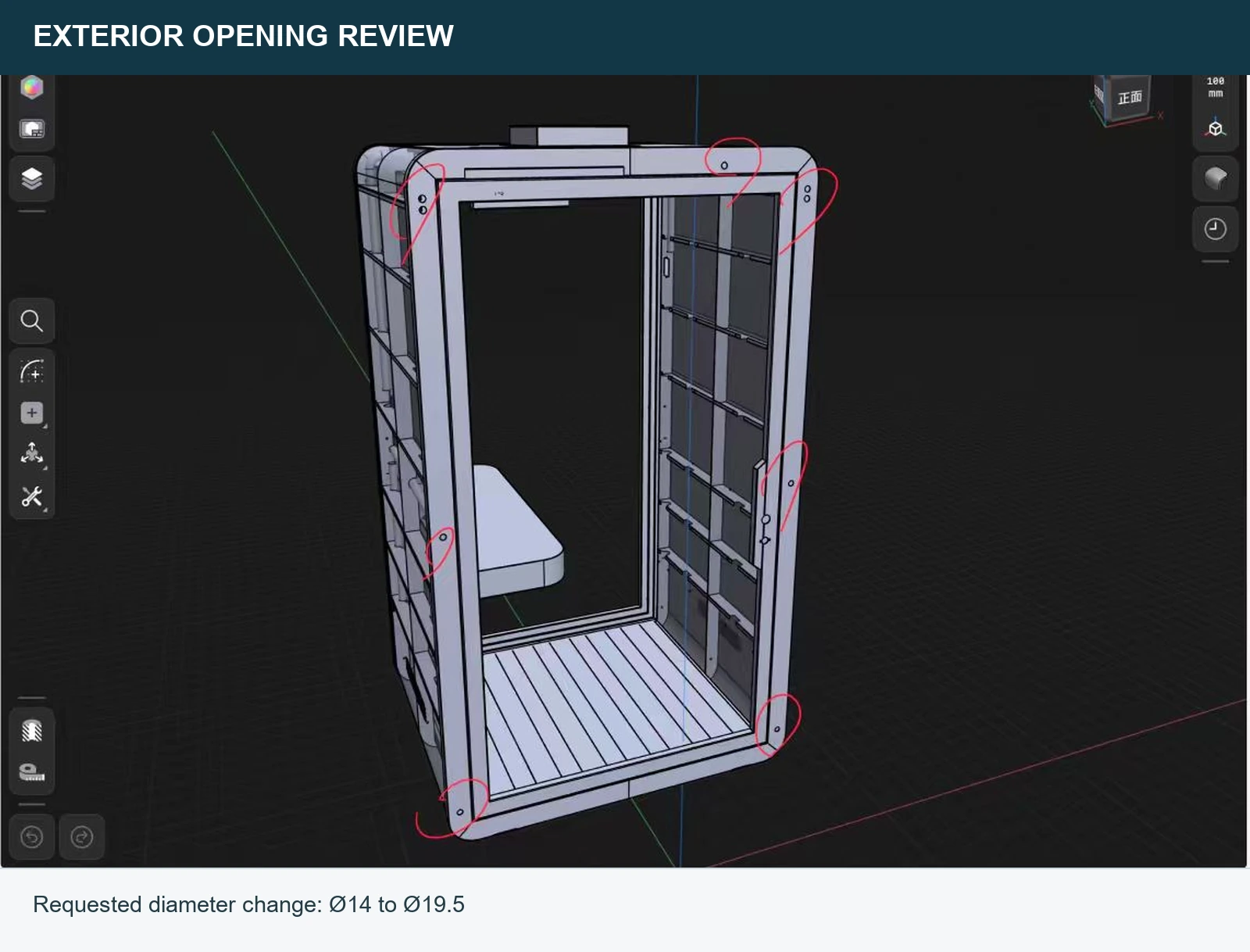
The supplied view circles several openings around the outer frame. The request gives a clear old and new diameter, but the drawing revision must still identify whether every circled location changes or whether different positions have different requirements. A manufacturing record should not rely on the color of a markup alone.
For the buyer, the useful check is simple: list each affected opening by a stable drawing reference, then confirm that the revised view and any hole schedule use the same value. This avoids applying one visible note to the wrong side, panel or repeated feature.
Tie lock-receiver adjustments to the correct reference
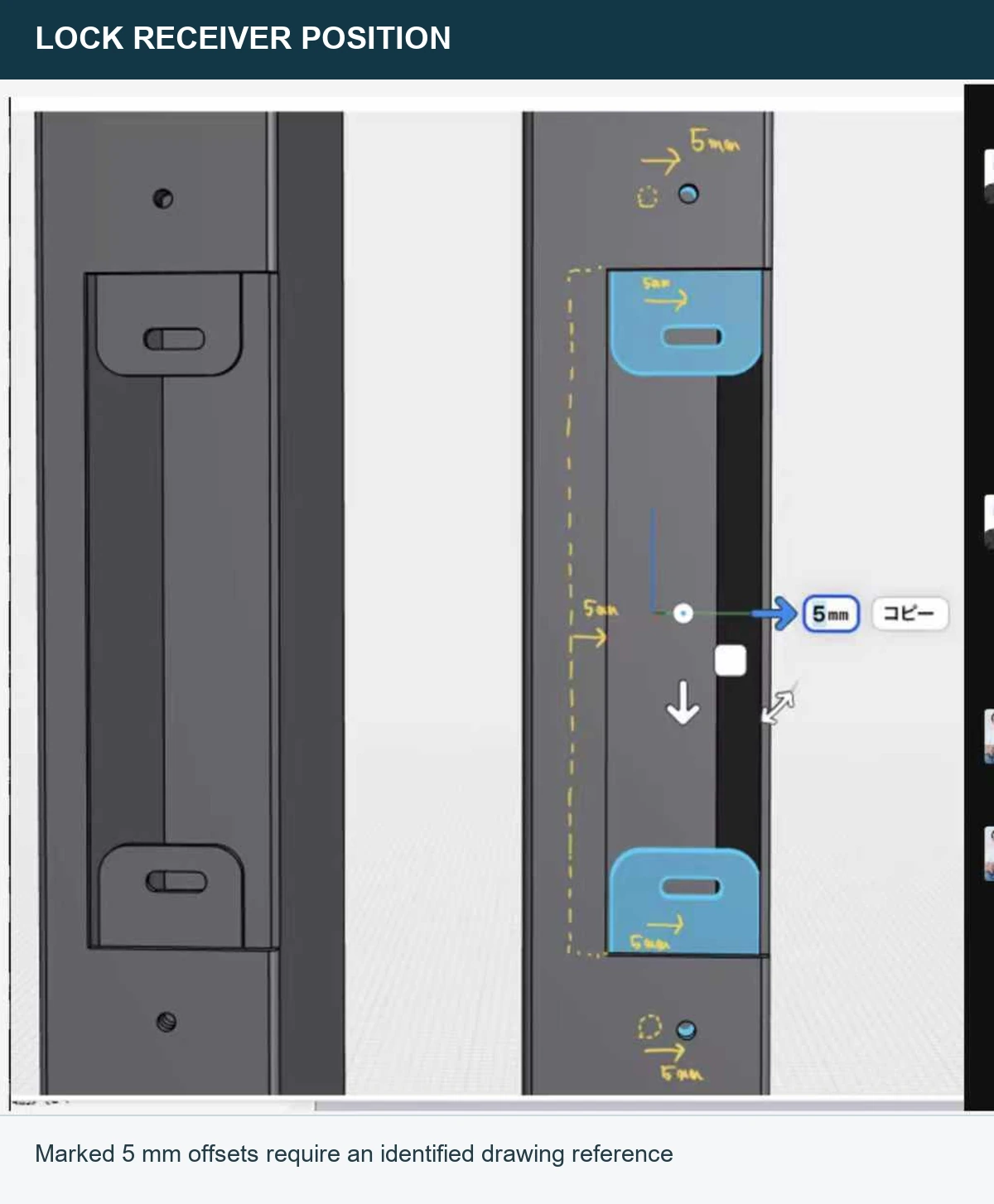
The request refers to an earlier ME model as the arrangement to review and reproduce. That makes the reference file part of the requirement: the project team needs the exact model name or drawing revision, not a general instruction to make the lock “like the previous one.”
The final record should state which receiver component moves, the direction and datum for each 5 mm note, and whether the change applies only to this project configuration. A project-specific request is not automatically a standard detail for every MobileX office pod.
Check the installed component envelope around an opening
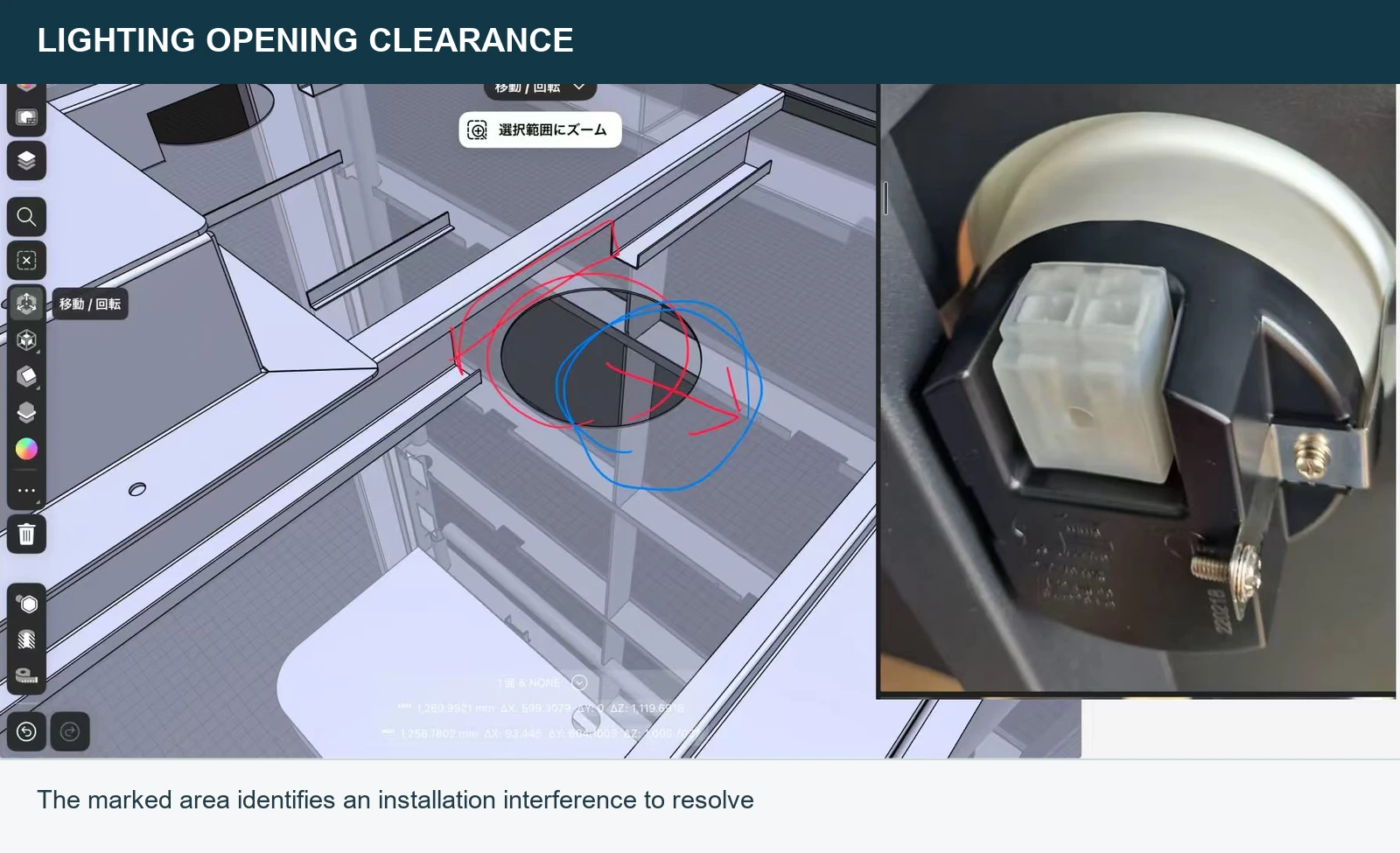
A circular opening can look adequate in plan while the installed component body, connector, clip or fixing reaches beyond it. In this review, the customer pointed to a nearby member that could contact the lighting component and asked for the opening position to be adjusted.
The useful drawing response is not only a moved circle. It should show the component envelope, a stable centre-location reference and the adjacent structure that controls clearance. If the hardware manufacturer provides an installation drawing, that information should be tied to the pod revision used for the decision.
Apply the same rule to the socket connection opening
Another marked view states that a socket connection screw may protrude and asks for the connection opening to move downward. The direction is understandable, but the supplied record does not provide a confirmed offset. Before manufacturing, the drawing needs the new centre position relative to a named datum and the relevant connector or screw projection.
Keep separate model references separate
The same client project also includes top-panel annotations in LM02v01.STEP, where Ø110 and Ø160 marks are visible. Their purpose, unit and position basis are not confirmed in the supplied record, so they remain in the private project change register rather than being presented here as an approved production detail.
Similarly, WI06v03.STEP and LM02v01.STEP should remain individually named in the review log. One project can contain several model references without those files being sequential revisions of the same object.
What this project record needs before production
- One consolidated change list tied to the correct model or drawing reference.
- Dimensions and positions measured from stable datums, including the applicable unit.
- Component references or installation envelopes for the lighting and socket interfaces.
- A clearly identified revised version and a record of the customer’s approval status.
- Separate manufacturing or physical-check evidence if the project later needs to document completion.
For the broader method used after drawing approval, see the custom modular pod change-order guide. It explains how to connect a request to its drawing revision, supply scope and decision to proceed.