Custom Office Pods: Top-Mounted Covers Designed Around Customer-Supplied Fire Extinguishers
Project answer: for this delivered custom project, the customer sent physical fire extinguishers to MobileX. MobileX used the supplied equipment dimensions to design top-mounted covers, then coordinated the covers, mounting interfaces, openings, fans and lights across several office pod sizes. The model records describe separate size configurations, not sequential revisions of one pod.
Multiple pod sizes, reviewed as separate configurations
Receiving the customer’s equipment established a physical reference for the cover geometry. It did not make every ceiling layout identical. Each pod-size configuration still needed its own arrangement for the device position, cover envelope, fan openings, light positions, structural divisions and available installation space.
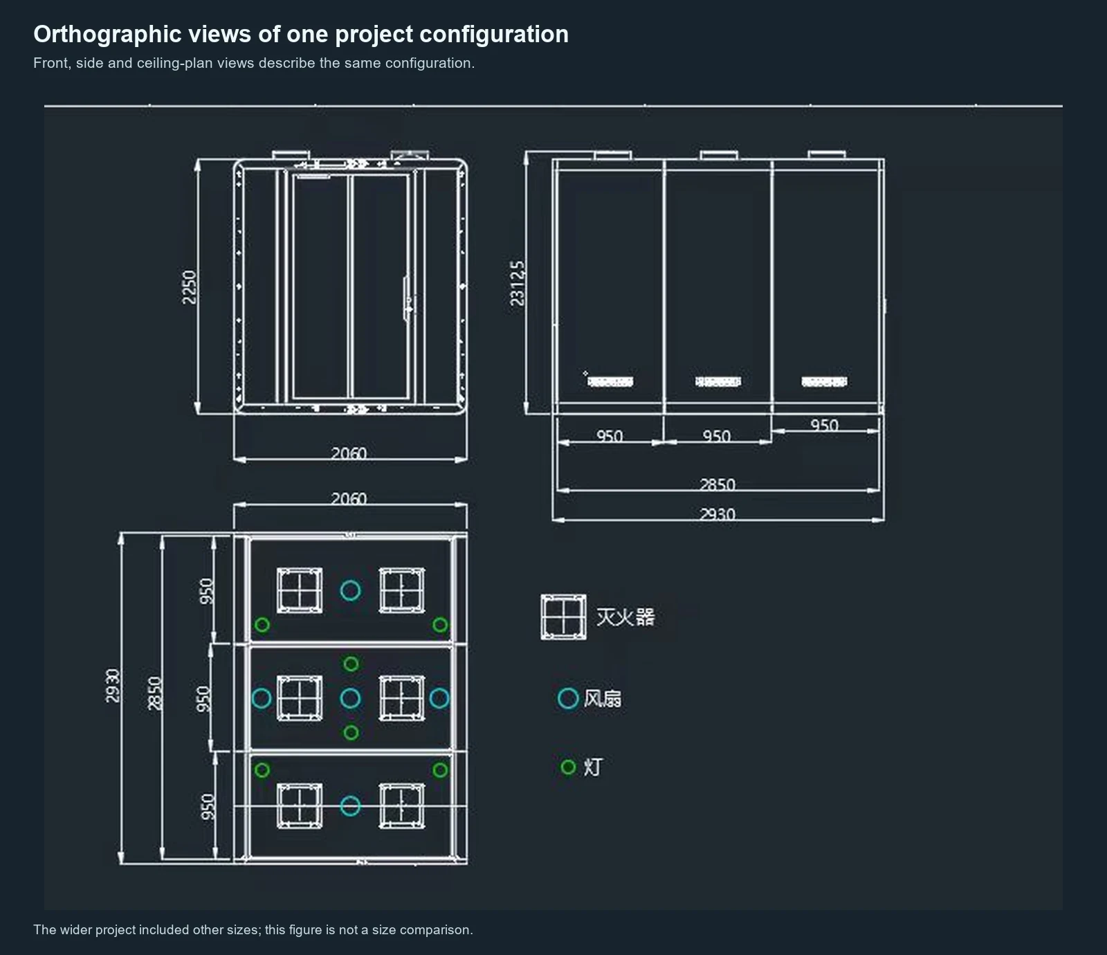
Coordinate the cover with fans, lights and panel divisions
A top-mounted cover occupies more than the circular or square symbol visible in plan. Its body and mounting arrangement need space above and around the ceiling interface. The top view therefore has to be read together with adjacent fans, lights and panel divisions.
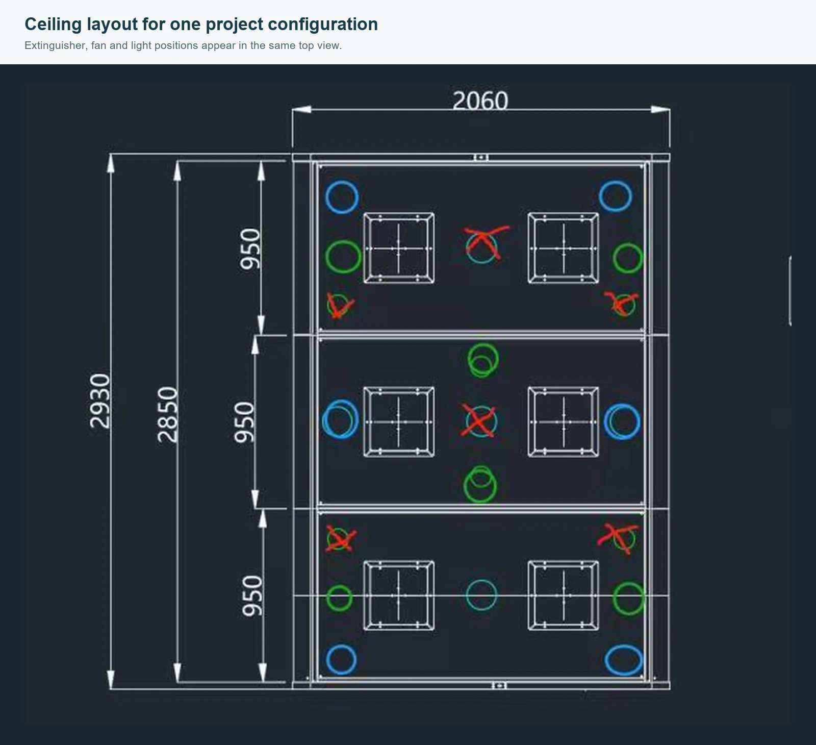
Fan position
Light position
Review mark
The marked plan shows repeated bays with separate equipment positions and review marks. It records the coordination work for that configuration rather than a standard ceiling layout for every office pod.
Check the complete cover envelope, not only the opening
Another project view compares the supplied equipment envelope with a proposed cover profile. This is the useful design question: does the cover provide room for the equipment body and mounting interface while staying compatible with the surrounding ceiling arrangement?
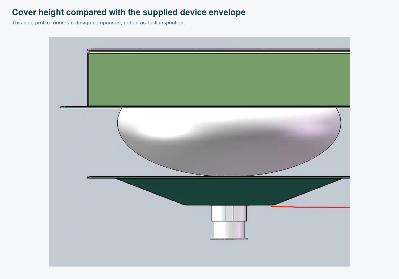
Keeping the supplied equipment body and the proposed cover profile in one side view allowed their height relationship to be reviewed before fabrication. The screenshot remains a design record and does not identify which marked alternative was used in the delivered units.
Connect the drawing detail to the supplied hardware
The interface record brings together a drawing view of curved mounting slots, a separate bracket sketch and a photograph of the physical bracket. That combination is more useful than a generic note to “add mounting holes” because it connects the top-panel detail to the hardware that the cover must accept.
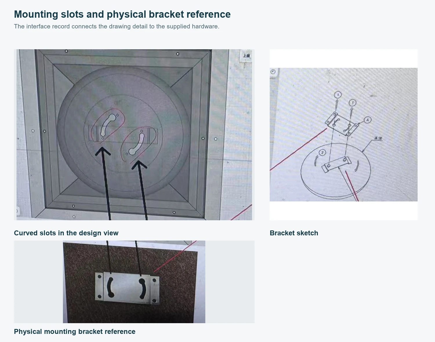
For production coordination, the useful record links the bracket orientation, slot pattern, hole locations and cover envelope to the correct model or drawing version. Different size configurations can share the same customer-supplied equipment while still needing different top-panel arrangements.
Project result
MobileX delivered the multi-size office pod project with top-mounted covers designed around the customer-supplied fire extinguishers. The drawings shown here document the cover geometry, ceiling layouts and mounting interfaces developed for the project.
Fire-safety scope boundary
The top-mounted cover is an equipment-accommodation component designed around the customer-supplied extinguisher dimensions. It is not presented as a fire-rated enclosure, a performance upgrade or a certified suppression system. This case makes no claim about extinguishing agent, activation method, fire class, coverage, installation height, testing or approval; those matters depend on the actual equipment documentation and the responsible building fire-safety review.
What buyers should define for a similar custom interface
- The physical device or an accurate manufacturer drawing, including its complete external envelope.
- The bracket, fixing pattern, connector and access needed for installation or removal.
- The applicable pod model and drawing version for every size being ordered.
- The proposed ceiling positions for the device, fans, lights and structural divisions.
- The division of responsibility between the office pod supplier, equipment supplier and site fire-safety professionals.
For the general method used to record and approve drawing changes, see the custom modular pod drawing-change guide. Buyers deciding whether the shell itself needs a different footprint or height can use the custom-size office pod site-fit guide. Fire-test, certification and site-approval evidence should be assessed separately through the office pod fire-safety evidence guide.